Tools and Test Equipment
≈ 10 min read · Print / save as PDF
Your multimeter is your eyes inside the circuit. Learn three settings first: DC volts (device on), beep/continuity and diode mode (device off). Your bench power supply is your second pair of eyes: its current display tells you what the board is doing.
A repair shop’s tools fall into three tiers. Students should own Tier 1 by Week 2 of the course. A new shop should open with Tier 1 and Tier 2. Tier 3 is added as board-level work grows.
Tool tiers
Tier 1 — Hand tools (module-level repair)
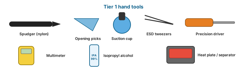
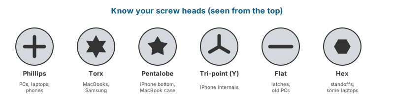
| Tool | Notes |
|---|---|
| Precision screwdriver set with these bits as a minimum: Phillips PH000, PH00, PH0, PH1; Torx T2, T3, T4, T5, T6, T8, T10; Pentalobe P2 (0.8 mm, iPhone bottom screws) and P5 (1.2 mm, MacBook bottom case); Tri-point Y000 (Y0.6) for iPhone internals; flat 1.5–2.5 mm; hex 1.5–2.5 mm | Quality matters: soft bits strip screws |
| Plastic spudgers, nylon pry tools, triangle picks (0.3–0.5 mm thick) | Opening cases and phones |
| Suction cup / handle and “iSclack”-style opener | Lifting phone screens |
| ESD-safe tweezers: straight, curved, fine-point | Handling small parts and connectors |
| Magnetic screw mat | Keeping screws in their original positions |
| Heat gun or heating pad / screen separator plate | Softening adhesive |
| Isopropyl alcohol 99%, lint-free wipes, ESD brushes | Cleaning |
| Adhesive strips and B-7000/T-7000 glue | Reassembly |
| Thermal paste and thermal pads (various thicknesses: 0.5, 1.0, 1.5, 2.0 mm) | Laptop/desktop cooling |
| Digital multimeter (see below) | Essential from day one |
| USB-C power meter (inline) | Shows voltage, current, and the PD profile negotiated |
| SATA/NVMe-to-USB adapters | Testing drives and recovering data |
| Bootable USB drives (see Chapter 8) | Diagnostics and OS installation |
Tier 2 — Soldering and diagnostic station (component-level repair)
| Tool | Notes |
|---|---|
| Temperature-controlled soldering station | Fine conical and knife/chisel tips. Cartridge-type stations (with the heater built into the tip) heat faster and handle small pads better |
| Hot-air rework station | Adjustable temperature and airflow; nozzles of several sizes |
| Stereo microscope, 7–45× zoom, with ring light | Indispensable for phone boards and inspection |
| Bench DC power supply, 0–30 V / 0–5 A (or more), with mA-resolution current display | Phone diagnostics, short injection, laptop board power |
| PCB holder / board clamp | Holds boards steady under the microscope |
| Fume extractor | Mandatory for health |
| Flux (no-clean gel/paste), solder wire (0.3–0.5 mm), solder paste, desoldering wick | Consumables |
| Kapton (polyimide) tape and aluminium tape | Heat shielding of nearby parts |
| Ultrasonic cleaner | Liquid-damage boards |
| Preheater / heat plate | Board preheating, phone screen separation |
Tier 3 — Advanced
| Tool | Notes |
|---|---|
| Thermal camera | Finds shorted components and overheating parts instantly |
| Oscilloscope (2-channel, ≥50 MHz) | Checking clocks, PWM switching, data lines |
| SPI flash programmer (e.g. CH341A-type with clip, or better) | Reading/writing BIOS chips |
| BGA reballing stencils and station | Advanced reballing |
| Phone-specific programmers (for battery health data, True Tone/display data, Face ID dot projector data) | iPhone module repairs (Chapter 15) |
| Back-glass laser machine | iPhone back-glass replacement on models without removable back glass |
| Screen separating / OCA laminating machine | Glass-only refurbishing (advanced, specialised) |
| Diagnostic boot software and repair-information subscriptions | Schematics, boardviews, known-good values |
The digital multimeter (DMM) in depth
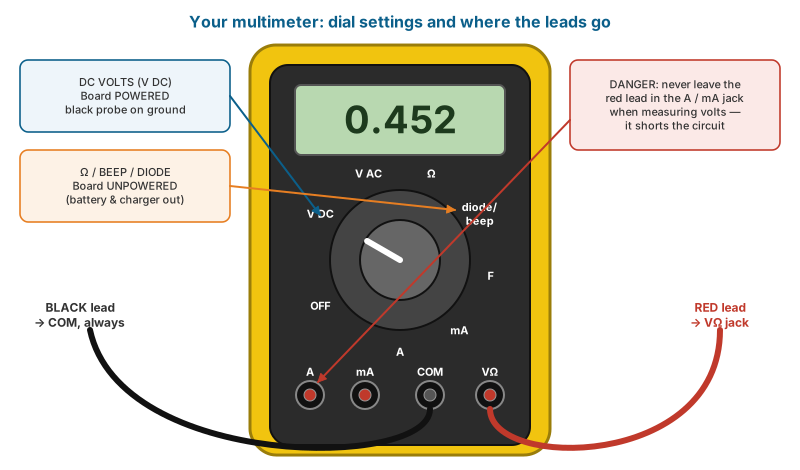
The multimeter is the most important instrument in the shop. Buy a true-RMS, auto-ranging meter with fast continuity beep and diode mode. Probes should have fine, sharp tips; add needle-tip probes for phone boards.
Functions you will use
| Function | Symbol | Use in repair |
|---|---|---|
| DC voltage | V DC | Measure rails on a powered board |
| AC voltage | V AC | Mains checks (with care) |
| Resistance | Ω | Check fuses, resistors, shorts on an unpowered board |
| Continuity | speaker icon | Fast beep test for opens, broken traces, blown fuses |
| Diode mode | diode symbol | Test diodes, MOSFETs, and compare “diode readings” of rails and lines against a known-good board |
| DC current | A / mA | Measure current (meter in series) — usually better done with the bench supply’s display |
| Capacitance | F (farad symbol) | Out-of-circuit capacitor checks |
Golden rules of measurement
Leaving the red lead in the A jack and then measuring voltage. It shorts the rail and can blow the meter fuse or damage the board.
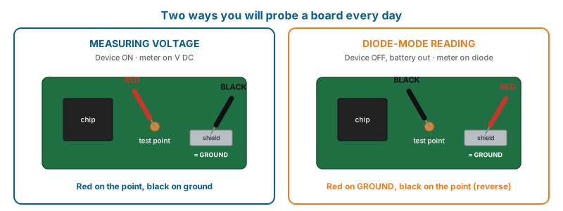
- Voltage is measured with the circuit powered; resistance, continuity and diode mode with the circuit unpowered (battery and adapter disconnected). Measuring resistance on a powered circuit gives wrong readings and can damage the meter.
- Black probe to ground for voltage measurements. Use a screw hole, shield, or large ground pad.
- Never leave the red lead in the A (current) socket when measuring voltage — that puts a near short across whatever you probe and can blow the meter fuse or damage the board.
- On tiny boards, keep probes perpendicular and steady to avoid bridging two adjacent pins.
Diode-mode measurement (“diode readings”)
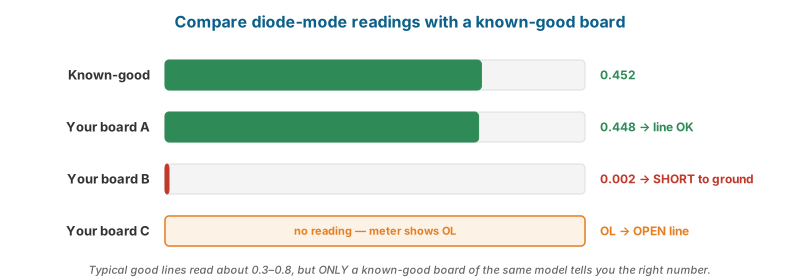
This technique is used throughout Chapters 11 and 16. With the board unpowered:
- Put the red probe on ground and the black probe on the test point (this is the convention used by most phone and laptop board technicians; it measures the reverse direction through the protection diodes built into the chips on that line).
- Read the value on the display (typically shown in volts or as a three-digit number such as 0.452 or 452).
- Compare with a known-good board of the same model, or with a published reference value.
How to interpret:
| Reading | Meaning |
|---|---|
| 0.000–0.005 | Short to ground |
| Very low compared to known-good (e.g. 0.080 where good is 0.400) | Partial short / leaking component |
| Normal (matches known-good within a few percent) | Line is probably fine |
| OL (open line) where a value is expected | Open circuit — broken trace, missing pad, failed connector pin, missing component |
Values are typical, not universal: most data and power lines on phones and laptops read somewhere between about 0.3 and 0.8 in this mode, but the only correct reference is a known-good unit of the same model and board revision.
Measuring resistance to ground
On large rails (e.g. a laptop CPU core rail, PPBUS, VBAT), resistance to ground may legitimately be low because of the load. CPU core rails can measure only a few ohms or less on a healthy board. A reading of 0–1 Ω on a rail that should be hundreds of ohms or more indicates a short. Again: compare with a known-good reference.
The bench DC power supply
A linear or switching lab supply with adjustable voltage and adjustable current limit. In repair it is used three ways:
- As a battery substitute for phones and laptops — powering the board through the battery connector (or a dedicated cable) while watching the current display. The current pattern during power-on is a powerful diagnostic signal (Chapter 16).
- As an adapter substitute for laptops — supplying 19–20 V through the DC jack with a current limit to see whether the board draws current, and how much.
- For short injection — feeding a low voltage into a shorted rail to heat the faulty component.
Short injection procedure
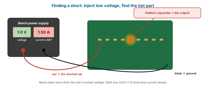
- Confirm the rail is shorted (diode mode / resistance near 0).
- Identify the rail’s normal operating voltage from the schematic. Never inject a voltage higher than the rail’s normal voltage, and stay at or below the lowest voltage rating of components on that rail. For low-voltage rails start at about 0.5–1 V.
- Set the current limit low (start around 0.5–1 A) and connect: red lead to the rail (a capacitor on that rail), black lead to ground.
- Raise the current gradually. The supply will be in current-limit (constant-current) mode because the short pulls the voltage down.
- Find the component that heats: thermal camera, a thin film of IPA (evaporates first over the hot part), rosin smoke (freeze-spray then watch where frost melts first), or a fingertip (carefully).
- Remove the hot component and re-measure. If the short is gone, replace it with a correct part.
Caution: If the short is inside a large chip (CPU, PMIC, SoC), injection will heat that chip. Do not inject high current for long into expensive ICs. Diagnose and decide.
Thermal camera
A thermal camera turns heat into a picture, showing shorted components within seconds of injection. Models designed for board repair have close-focus lenses. A smartphone-attachment thermal camera with a macro lens is an affordable starting point.
Microscope
Stereo zoom microscopes (7–45×) give depth perception, which you need for soldering. Mount it on a stable boom or pillar stand with an LED ring light. Optional: a trinocular port with a camera for recording work and teaching — very useful in a classroom.
Oscilloscope basics
Use an oscilloscope to see signals that change too fast for a multimeter:
- PWM switching at a buck converter’s phase node (a square wave confirms the controller is switching).
- Crystals/clocks (sine or square wave at the expected frequency).
- Data lines (activity bursts on SPI, I²C).
Set the probe to ×10, connect probe ground to board ground with the shortest possible lead, and use auto-set as a starting point.
Software toolkit
Keep these on a USB drive (preferably using a multi-boot tool such as Ventoy, which lets you copy several ISO files onto one drive and choose at boot):
| Tool | Purpose |
|---|---|
| Windows installation media (from Microsoft’s Media Creation Tool) | Clean install / repair |
| A Linux live system (e.g. Ubuntu) | Hardware testing, data recovery when Windows won’t boot |
| MemTest86 or Memtest86+ | RAM testing |
CrystalDiskInfo (Windows) / smartctl (Linux) |
Drive health (S.M.A.R.T.) |
| HWiNFO | Sensors, temperatures, hardware inventory |
| OCCT / Prime95 / FurMark | Stress testing CPU, GPU, PSU |
| Manufacturer diagnostics (e.g. Dell SupportAssist ePSA, Lenovo Diagnostics, HP PC Hardware Diagnostics UEFI) | Built-in or downloadable hardware tests |
| Rufus | Writing bootable USB drives |
| Android Platform Tools (ADB, Fastboot) | Android diagnostics and flashing |
| Manufacturer flashing tools (Samsung Odin; Google’s Android Flash Tool / factory images) | Android firmware |
| Apple Devices app (Windows) / Finder (macOS) / iTunes (older Windows) | iPhone restore |
| Apple Configurator (macOS) | DFU revive/restore of Apple-silicon Macs |
Watch and read
- Watch: Multimeter basics — YouTube search: how to use a multimeter for beginners
- Watch: Diode-mode readings on boards — YouTube search: diode mode measurement motherboard repair
- Watch: Short injection and thermal camera — YouTube search: finding short circuit on motherboard voltage injection thermal camera
- Read/use: SparkFun — How to Use a Multimeter — Beginner tutorial with photos.
- Read/use: OpenBoardView — Free viewer for boardview files.
Review questions
- Why must resistance and diode-mode measurements be taken with the device unpowered?
- In the diode-mode technique described, which probe goes to ground?
- A data line reads OL in diode mode while the known-good reads 0.520. What does this indicate?
- Describe the safety limits when injecting voltage into a shorted rail.
- Name three methods to locate a heating component during short injection.
Lab exercises
Lab 3.1 — Multimeter drills. Measure: a 9 V battery, a USB port’s 5 V, ten resistors (compare to code), continuity of a ribbon cable, and the forward voltage of a silicon diode, a Schottky diode and an LED.
Lab 3.2 — Known-good database. Using two identical scrap boards (one working), record diode-mode readings on 20 points (charge port pins, battery connector pins, main rails). Start your own reference notebook — a technician’s known-good database is one of their most valuable assets.
Lab 3.3 — Short injection. On a scrap board, the instructor creates a short by soldering a deliberately shorted capacitor onto a low-voltage rail. Locate it using injection and a thermal camera or IPA.