Electronics Fundamentals
≈ 12 min read · Print / save as PDF
You only need four ideas to start: voltage pushes, current flows, resistance slows the flow, and power is the work done. Almost every fault you will fix is either a SHORT (power leaking straight to ground) or an OPEN (a broken path).
You cannot diagnose what you do not understand. This chapter gives the electrical theory and component knowledge that every later chapter depends on. Learn the formulas; you will use them daily.
Voltage, current, resistance and power
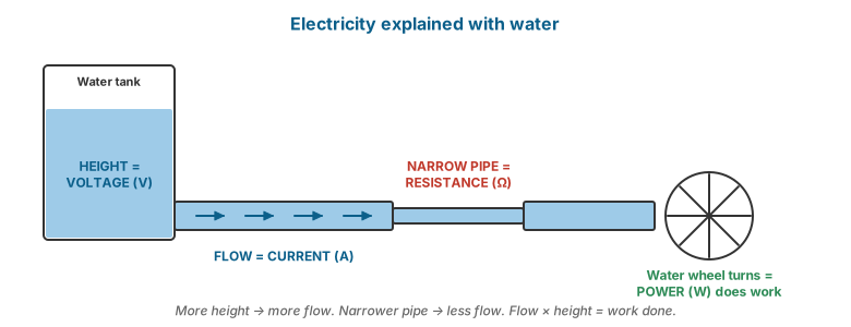
| Quantity | Symbol | Unit | Analogy (water in a pipe) |
|---|---|---|---|
| Voltage (potential difference) | V (or U) | volt (V) | Water pressure |
| Current | I | ampere (A) | Flow rate |
| Resistance | R | ohm (Ω) | Narrowness of the pipe |
| Power | P | watt (W) | Work done per second |
Ohm’s law
Power law
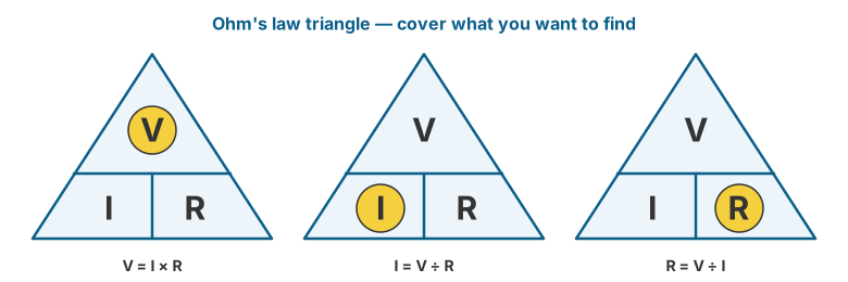
Worked example 1. A phone board draws 0.5 A from a 4.0 V supply. Power = 4.0 × 0.5 = 2.0 W.
Worked example 2. A laptop rail at 19 V is shorted to ground through a failed capacitor with an internal resistance of 0.1 Ω. Theoretical current = 19 / 0.1 = 190 A. In reality the adapter’s current limit or protection will shut down first — but this shows why a short makes an adapter “click” or an LED blink, and why injecting voltage into a short must be done with a current-limited bench supply.
Worked example 3. Why do we inject low voltage to find shorts? If a short has 0.5 Ω resistance and we inject 1 V with a current limit of 2 A: I = 1 / 0.5 = 2 A, P = 1 × 2 = 2 W — enough to warm the shorted component so a thermal camera or IPA can find it, without burning traces.
Units and prefixes
| Prefix | Symbol | Multiplier | Example |
|---|---|---|---|
| mega | M | 10⁶ | 1 MΩ = 1,000,000 Ω |
| kilo | k | 10³ | 4.7 kΩ = 4,700 Ω |
| milli | m | 10⁻³ | 250 mA = 0.25 A |
| micro | µ (u) | 10⁻⁶ | 10 µF |
| nano | n | 10⁻⁹ | 100 nF = 0.1 µF |
| pico | p | 10⁻¹² | 22 pF |
DC and AC
- DC (direct current) flows in one direction. Everything inside a computer and phone runs on DC.
- AC (alternating current) reverses direction periodically. Philippine mains is 220–230 V, 60 Hz.
- A power supply (PSU, adapter, charger) converts AC mains to the DC voltages the device needs.
Series and parallel circuits
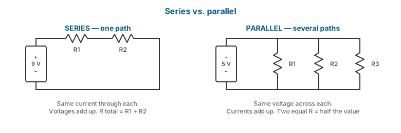
Series — same current flows through each component; voltages add.
Parallel — same voltage across each component; currents add.
Two equal resistors in parallel give half the value. This matters in diagnosis: when you measure resistance across a capacitor on a board, you are measuring it in parallel with everything else connected to that rail, which is why in-circuit readings differ from component data-sheet values.
Voltage divider
Voltage dividers set the output of nearly every voltage regulator on a motherboard (the feedback network). A failed feedback resistor can make a regulator output the wrong voltage.
Ground, rails, and short circuits
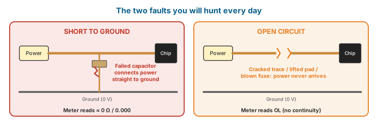
- Ground (GND) is the 0 V reference. On boards, all large copper areas, metal shields and screw holes are normally ground.
- A rail (or power line) is a named net that carries a specific voltage to many components — e.g.
PP3V3,VCC_CORE,VBAT,PPBUS,+5VALW. - A short circuit (“short to ground”) means a rail has an unintended very low resistance path to ground — usually a failed capacitor, a failed chip, or a solder bridge.
- An open circuit means a path is broken — a cracked trace, a lifted pad, a blown fuse, a broken solder joint.
Most board-level faults are one of these two: a short where there should be none, or an open where there should be continuity.
Passive components
Resistors
Resist current flow; used for current limiting, voltage division, pull-up/pull-down of signals, and sensing current (very low-value “shunt” or sense resistors).
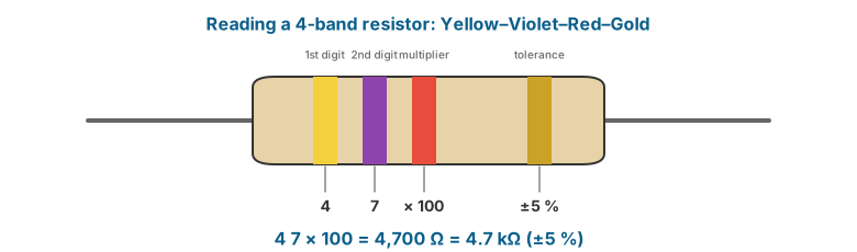
Through-hole colour code (4-band): band 1 = first digit, band 2 = second digit, band 3 = multiplier, band 4 = tolerance.
| Colour | Digit | Multiplier |
|---|---|---|
| Black | 0 | ×1 |
| Brown | 1 | ×10 |
| Red | 2 | ×100 |
| Orange | 3 | ×1k |
| Yellow | 4 | ×10k |
| Green | 5 | ×100k |
| Blue | 6 | ×1M |
| Violet | 7 | ×10M |
| Grey | 8 | — |
| White | 9 | — |
| Gold | — | ×0.1 (tolerance ±5%) |
| Silver | — | ×0.01 (tolerance ±10%) |
Example: Yellow–Violet–Red–Gold = 4, 7, ×100 = 4,700 Ω = 4.7 kΩ ±5%.
SMD resistor codes:
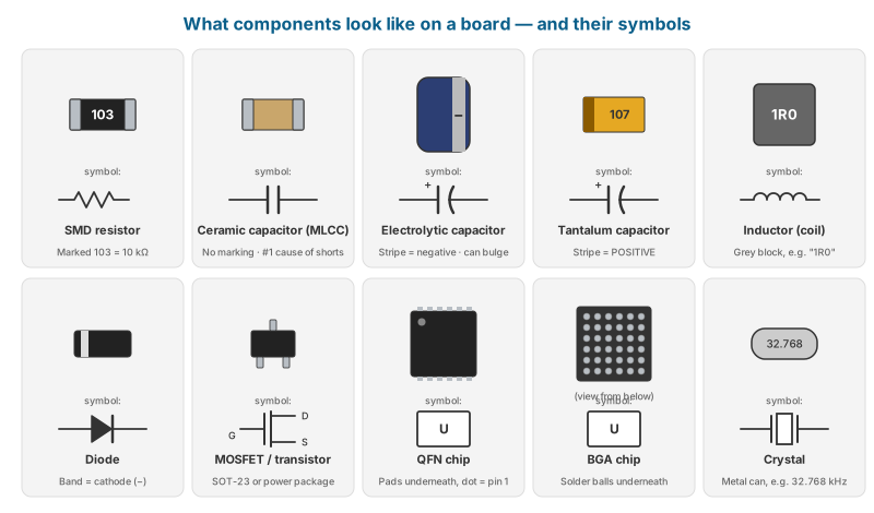
- 3-digit: first two digits + number of zeros.
103= 10 × 10³ = 10 kΩ.472= 4.7 kΩ. - 4-digit: first three digits + number of zeros.
1002= 10 kΩ. Rmarks the decimal point:4R7= 4.7 Ω;R010= 0.010 Ω (a current-sense resistor).000or0= zero-ohm link (a jumper).- EIA-96 code (two digits + letter) is used on small 1% resistors; look it up in Appendix A.
- The smallest resistors in phones (0201 and 01005 sizes) are unmarked — you rely on the schematic.
Capacitors
Store charge; used to filter (smooth) power rails, decouple noise near chips, couple AC signals, and time circuits.
- Ceramic (MLCC) — the small tan/brown/grey blocks that cover every board. Unpolarised. Most common cause of rail shorts: an MLCC cracks or fails internally and shorts the rail to ground.
- Electrolytic (aluminium) — cylindrical, polarised, on desktop motherboards and PSUs. Fail by bulging, leaking, or drying out. Bulging tops on old motherboards are a classic visible fault.
- Polymer/tantalum — rectangular, polarised (stripe or bevel marks the positive end on tantalum), used near CPU/GPU power stages and in laptops. Tantalums often fail short.
Ratings to note: capacitance (µF/nF/pF), voltage rating (always replace with equal or higher), and for electrolytics, temperature and ESR.
Diagnosis tip: In a short, the failed capacitor is usually physically small and somewhere on the shorted rail. With a current-limited supply injecting into the rail, it becomes the hottest spot.
Inductors (coils, chokes)
Store energy in a magnetic field; essential in switching voltage regulators (buck converters). On boards they appear as square grey/black blocks next to MOSFETs, often marked with values like R22 (0.22 µH), 1R0 (1.0 µH), 2R2 (2.2 µH). An inductor itself rarely fails, but the voltage on the output side of a regulator’s inductor is the regulator output, making it a convenient measurement point.
Fuses on boards look like small resistors (often marked with a letter code or unmarked) and protect inputs — USB, keyboard, fan, charging input. A blown fuse reads open-circuit.
Semiconductors
Diodes
Allow current in one direction only. The anode (+) to cathode (−) direction conducts; the cathode is marked with a band.
- Forward voltage drop: about 0.6–0.7 V for silicon diodes, about 0.2–0.4 V for Schottky diodes.
- Zener / TVS diodes clamp voltage spikes; used on USB, charge ports and data lines. TVS diodes frequently fail short after a voltage surge (e.g. a bad charger), shorting a charging line.
- LEDs emit light; forward voltage depends on colour (roughly 1.8–2 V red, around 3 V white/blue).
The multimeter’s diode mode applies a small test current and displays the voltage drop. This is the basis of the “diode-mode measurement” technique used in board repair (Chapter 3).
Transistors and MOSFETs
MOSFETs (metal-oxide-semiconductor field-effect transistors) are electronic switches. Three terminals: Gate (G), Drain (D), Source (S). A voltage on the gate turns the drain-source path on or off.
- N-channel MOSFET — turns on when gate is higher than source (typically used as low-side switches and in buck regulators).
- P-channel MOSFET — turns on when gate is lower than source (often used as high-side “load switches” that enable a rail).
Where you meet them:
- Buck converter power stages — pairs of MOSFETs (high-side and low-side) that, with an inductor and capacitors, step a higher voltage down to a lower one (e.g. 19 V → 1.0 V for the CPU core).
- Load switches — enable rails during the power-up sequence.
- Charging path — laptop charger circuits use MOSFETs to select between adapter and battery power.
Failure mode: MOSFETs commonly fail short drain-to-source, putting the input voltage on the output, or shorting the input rail to ground.
Integrated circuits (ICs)
Chips containing many transistors. Common ones in repair:
| IC type | Role |
|---|---|
| CPU / SoC | Processor; in phones the SoC contains CPU, GPU, modem (sometimes), and memory controller |
| PCH / chipset | On PCs/laptops, handles I/O (USB, SATA, audio, etc.) |
| PMIC / PMU | Power-management IC — generates many rails in phones and some laptops |
| PWM controller | Controls buck converters (e.g. the CPU VCORE controller) |
| Charger IC | Manages battery charging and power-path selection |
| EC / SMC / KBC | Embedded controller — the “always-on” microcontroller in laptops that handles the power button, battery, fans and keyboard |
| BIOS/UEFI flash | SPI flash chip (often 8-pin SOIC or WSON package) holding firmware |
| NAND / eMMC / UFS / NVMe | Storage |
| RAM (DRAM / LPDDR) | Memory |
| USB-C PD controller | Negotiates USB-C power delivery and data roles |
| Level shifters, logic gates | Translate signals between voltage domains |
Crystals and oscillators
Provide clock signals. A missing clock stops a processor from running. Common frequencies: 32.768 kHz (real-time clock), 24 MHz / 25 MHz / 19.2 MHz (system clocks). A crystal cannot be checked reliably with a multimeter; an oscilloscope is needed.
Component packages
| Package | Description | Where |
|---|---|---|
| Through-hole (THT) | Leads pass through holes | PSUs, older boards, connectors |
| 1206, 0805, 0603 | SMD passives (imperial size in hundredths of an inch: 0603 = 0.06 × 0.03 in) | Desktop boards |
| 0402, 0201 | Tiny SMD passives | Laptop and phone boards |
| 01005 | Smallest common passive (0.4 × 0.2 mm) | Phone boards |
| SOT-23 | Small 3–6-pin transistor package | Everywhere |
| SOIC / SOP | Gull-wing leaded IC | BIOS chips, older ICs |
| QFN / DFN | Leadless, pads underneath, often with a centre thermal pad | Regulators, controllers |
| BGA | Ball-grid array — solder balls under the chip | CPU, GPU, PCH, SoC, RAM, NAND, PMIC |
Digital signals and buses (what you’ll see on schematics)
| Bus / signal | Description |
|---|---|
| I²C (SDA, SCL) | Two-wire low-speed bus; used for sensors, battery fuel gauges, charging ICs, display/touch controllers. Requires pull-up resistors to a rail; lines idle “high” |
| SPI (CLK, MOSI, MISO, CS) | Four-wire bus; BIOS flash chips |
| SMBus | I²C variant; laptop battery communication |
| PCIe | High-speed lanes: GPU, NVMe, Wi-Fi |
| MIPI DSI / CSI | Display and camera interfaces in phones |
| eDP | Embedded DisplayPort, laptop panels |
| USB 2.0 (D+, D−) / USB 3.x (TX/RX pairs) | Data |
| Enable (EN), Power-Good (PG / PGOOD) | Power sequencing — one regulator’s PG enables the next |
| RESET, PWRBTN# | Control signals; # or _L suffix usually means active-low |
Reading schematics and boardviews
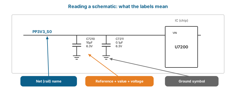
A schematic is the circuit diagram — what connects to what, with component references (R1234, C5678, U3100, Q7200), values, and net (rail/signal) names. A boardview file shows the physical layout of the board — where each component and test point sits, and which net each pad belongs to. Boardview software (for example OpenBoardView, which is free) lets you click a pad and see every other pad on the same net.
Reading a schematic:
- Find the block diagram / table of contents page to locate the power section.
- Find the power sequence page if provided — it lists which rails come up in which order.
- Follow rails by name. A net name appearing on two pages means those points are connected.
- Look at the values: capacitor voltage ratings tell you approximately what voltage a rail carries.
- Note
NC(not connected / not stuffed) components — present on the schematic but not fitted.
Reference designator letters:
| Letter | Component |
|---|---|
| R | Resistor |
| C | Capacitor |
| L | Inductor |
| D | Diode |
| Q | Transistor / MOSFET |
| U | Integrated circuit |
| F | Fuse |
| J / CN | Connector |
| Y / X | Crystal |
| TP / PP | Test point |
| FL | Filter |
Where to get schematics and boardviews: Manufacturers rarely publish them. Repair technicians obtain them through paid repair-information subscriptions and diagnostic software suites, and through technician communities. Respect the licensing terms of whatever source you use. Apple publishes official repair manuals (not schematics) for supported iPhone and Mac models on its Self Service Repair site; many PC manufacturers (Dell, Lenovo, HP) publish free service manuals with disassembly steps and part numbers.
How a switching regulator works (buck converter)
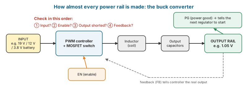
Almost every rail in a modern device is made by a buck (step-down) converter:
- The input (e.g. 19 V or 12 V or battery 3.8 V) feeds a high-side MOSFET.
- A PWM controller switches the MOSFET on and off rapidly (hundreds of kHz to a few MHz).
- The inductor and output capacitors smooth the pulses into a steady lower DC voltage.
- A feedback divider tells the controller the actual output so it can regulate.
- The controller needs an input voltage, an enable (EN) signal, and often its own supply (VCC) before it runs. When the output is stable, it asserts power-good (PG).
So when a rail is missing, check in order: Is the input present? Is the enable present? Is the output shorted? Is the feedback correct? Only then suspect the controller.
Watch and read
- Watch: Ohm’s law explained — YouTube search: ohm’s law explained for beginners
- Watch: Reading schematics — YouTube search: how to read a schematic for repair beginners
- Watch: How a buck converter works — YouTube search: buck converter explained simply
- Read/use: All About Circuits — free textbook — Complete free electronics textbook: DC, AC, semiconductors, digital.
- Read/use: Training Regulations: Electronic Products Assembly and Servicing NC II (PDF) — The official standard for board-level electronics: assemble, service consumer electronics, service industrial modules.
Review questions
- A rail measures 1.05 V and the component draws 15 A. What power does it consume?
- Decode: SMD resistors marked
222,4R7,R005,1001. - Which component most often causes a short to ground on a modern board, and why?
- Explain the difference between N-channel and P-channel MOSFETs in terms of gate voltage.
- What four conditions does a buck converter need to produce its output?
- What is the difference between a schematic and a boardview?
Lab exercises
Lab 2.1 — Ohm’s law verification. Build a series circuit of two resistors on a breadboard with a 5 V supply. Calculate and then measure the current and each resistor’s voltage drop. Record the percentage error.
Lab 2.2 — Component identification. On a scrap laptop board, identify and label 10 examples each of: MLCC capacitors, resistors, inductors, MOSFETs, and ICs. Record reference designators if visible.
Lab 2.3 — Schematic tracing. Given a schematic for a laptop (provided by the instructor), trace the path of the battery/adapter input to the system rail, listing every fuse, MOSFET and sense resistor on the way.