Laptop Architecture and Disassembly
≈ 5 min read · Print / save as PDF
A laptop makes all its own power from one input. It has a small always-on controller (the EC) that wakes everything else when you press the button. Always disconnect the battery first and keep a screw map.
How a laptop differs from a desktop
| Aspect | Desktop | Laptop |
|---|---|---|
| Power input | Separate PSU produces all rails | Single DC input (barrel jack 19–20 V, or USB-C PD up to 20 V; up to 48 V with USB PD EPR on some high-power models); the motherboard makes all rails |
| Battery | None (except CMOS coin cell) | Li-ion pack, typically 2–4 cells in series (2S ≈ 7.4–7.7 V nominal, 3S ≈ 11.1–11.55 V, 4S ≈ 14.8–15.4 V) |
| Always-on controller | Standby circuit in PSU | Embedded Controller (EC) on the board, always powered |
| Components | Modular | Often soldered: CPU, GPU, RAM (LPDDR), sometimes storage |
| Cooling | Large heatsinks, many fans | Heat pipes, 1–2 fans, thermal pads |
| Display | External | Internal panel via eDP cable |
Battery terminology
- Nominal voltage per Li-ion cell: about 3.6–3.85 V; fully charged: 4.2 V for standard cells, up to about 4.35–4.45 V for high-voltage cells; discharge cut-off: around 3.0 V.
- Capacity in Wh (watt-hours) = nominal voltage × Ah. Example: 11.55 V × 4.5 Ah ≈ 52 Wh.
- Cycle count and design vs. full-charge capacity (wear) are reported by the battery’s fuel gauge over SMBus. In Windows, run
powercfg /batteryreportto generate an HTML report showing design capacity, full charge capacity and cycle count. On macOS: System Settings → Battery → Battery Health; or System Information → Power for cycle count.
Laptop power architecture (generic)
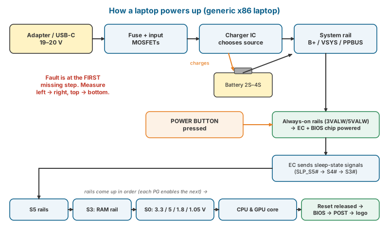
The following is the general structure used by most x86 laptops. Names and exact voltages differ by manufacturer — always use the schematic.
- Adapter input (DCIN / VIN / VADP). Barrel jack (19–20 V) or USB-C via a PD controller that negotiates 5/9/15/20 V.
- Input protection and selection: fuse, input MOSFETs controlled by the charger IC. The charger IC decides whether the system runs from adapter or battery and charges the battery.
- System rail (often called B+, VSYS, or on Intel-era MacBooks PPBUS_G3H): the main power bus fed by adapter or battery.
- Always-on rails (e.g. 3VALW/5VALW on many PC laptops; PP3V42_G3H on Intel MacBooks): created as soon as power is present; they power the EC, the power button circuit and the BIOS chip.
- Power button pressed → EC sees the signal → EC asserts sleep-state signals to the chipset/regulators.
- Sequenced rails come up: S5 rails → S3 rails (RAM: e.g. 1.2 V for DDR4, 1.1 V for DDR5; LPDDR rails lower) → S0 rails (3.3 V, 5 V system, 1.8 V, 1.05 V, etc.).
- CPU core (VCORE / VCCIN) and GPU core rails start last, controlled by a multiphase PWM controller using voltage requests from the CPU (VID).
- Reset released → CPU fetches BIOS from the SPI flash → POST → display.
A board that “doesn’t turn on” is stuck somewhere in this chain. Chapter 11 shows how to find the point of failure by measuring.
USB-C power delivery essentials
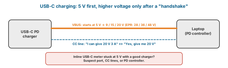
- USB-C carries 5 V by default. Higher voltages are only provided after a USB Power Delivery (PD) negotiation between the charger and the laptop’s PD controller over the CC line.
- Standard Power Range (SPR) fixed voltages: 5, 9, 15, 20 V up to 100 W (20 V × 5 A with a 5 A e-marked cable). Extended Power Range (EPR): 28, 36, 48 V up to 240 W.
- An inline USB-C meter shows the negotiated voltage. If a laptop stays at 5 V with a known-good PD charger, the negotiation is failing: suspect the PD controller, the CC lines, the port itself, or the PD controller’s firmware/power.
- A device that pulls 20 V but draws almost no current is negotiating correctly but not charging — suspect the charger IC, the battery, or the power path.
Disassembly principles
Photograph every stage with your phone and keep the photos with the job order. They are your reassembly guide and your evidence if a customer disputes the condition.
- Find the service manual (Dell, Lenovo, HP and others publish them free on their support sites; Apple publishes manuals for supported Macs in its Self Service Repair programme). Follow the documented order.
- Remove the battery or disconnect it first. Many modern laptops have an internal battery — the bottom cover must come off first, then immediately disconnect the battery connector. Some laptops have a “battery disconnect/ship mode” setting in BIOS that is useful when the connector is hard to reach.
- Photograph each stage. Record screw positions on a screw map.
- Hidden screws are often under rubber feet, labels, or the keyboard.
- Clips: pry along the seam with a plastic pick, starting at a corner or near the hinge; avoid metal tools on painted aluminium.
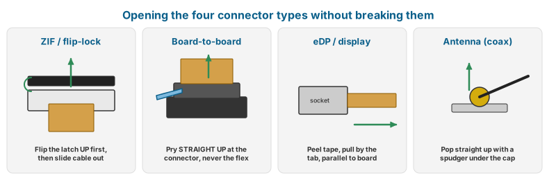
- Connectors: ZIF/FPC (lift the flip lock), press-fit/board-to-board (pry straight up), LVDS/eDP (pull by the tab, parallel to the board), antenna (pop straight up with a spudger).
- Keyboard replacement: on many laptops the keyboard is riveted or glued into the top case (palmrest). The repair then becomes either replacing the whole top case assembly or drilling/melting rivets and fixing the new keyboard with screws — a common but time-consuming shop service. Quote accordingly.
Watch and read
- Watch: Laptop teardown technique — YouTube search: laptop disassembly tutorial
- Read/use: Dell manuals — Free service manuals with disassembly steps and part numbers.
- Read/use: Lenovo PSREF — Exact specifications and compatible parts for every Lenovo model.
- Read/use: HP Support — Maintenance and service guides, drivers and diagnostics.
Review questions
- What is the nominal voltage of a 3S Li-ion laptop pack, and what is its fully charged voltage with standard 4.2 V cells?
- Describe the role of the embedded controller.
- A USB-C laptop charger shows 5 V on a USB-C meter and never 20 V. Name four suspects.
- Why must you consult the service manual before disassembly?
Lab exercises
Lab 9.1 — Battery report. Generate powercfg /batteryreport on three laptops and calculate each battery’s wear percentage: (1 − full charge capacity / design capacity) × 100.
Lab 9.2 — Full teardown. Fully disassemble and reassemble a laptop to the bare motherboard using the service manual, with a complete screw map. Must power on and pass QC afterwards.