PC Architecture, Components and Assembly
≈ 6 min read · Print / save as PDF
A desktop is a set of parts that plug together. Most build problems come from parts that do not match (socket, RAM type, BIOS version) or cables in the wrong place.
The major components
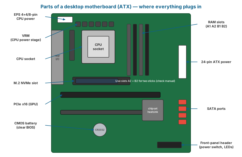
| Component | Function | Key specifications |
|---|---|---|
| CPU | Executes instructions | Socket (e.g. Intel LGA1700, LGA1851; AMD AM4, AM5), core count, TDP |
| Motherboard | Connects everything | Socket, chipset, form factor (ATX, Micro-ATX, Mini-ITX), RAM type, M.2 slots |
| RAM | Working memory | Type (DDR4, DDR5), capacity, speed, channel configuration |
| Storage | Permanent data | HDD (SATA), SATA SSD, NVMe SSD (M.2 PCIe) |
| GPU | Graphics | Integrated (in the CPU) or discrete (PCIe card); power connectors |
| PSU | Converts AC to DC rails | Wattage, efficiency rating (80 PLUS), connectors, ATX 3.x for modern GPUs |
| Cooling | Removes heat | Air coolers, AIO liquid coolers, case fans |
| Case | Housing and airflow | Form-factor support, GPU length, cooler height clearance |
Compatibility rules
- CPU ↔︎ motherboard socket and chipset. The socket must match physically, and the board’s BIOS must support that CPU generation. A board may need a BIOS update before it will POST with a newer CPU of the same socket — check the board’s CPU support list on the manufacturer’s site. Some boards offer a “BIOS Flashback” feature that updates from a USB drive without a CPU installed.
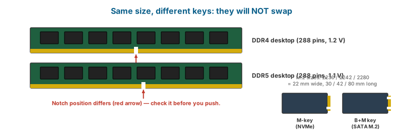
- RAM type. DDR4 and DDR5 desktop modules both have 288 pins but the notch is in a different position — they are physically incompatible. A board supports one or the other (DDR4 runs at 1.2 V nominal; DDR5 at 1.1 V nominal, with on-module power management).
- Storage interfaces. M.2 slots are keyed: M-key for NVMe (and some SATA) SSDs, B+M-key drives fit both; check whether the slot supports PCIe NVMe, SATA M.2, or both. M.2 lengths: 2242, 2260, 2280 (most common).
- GPU power and size. Check the card’s power connectors (6-pin, 8-pin PCIe, or the 12VHPWR / 12V-2x6 16-pin connector) and the PSU’s recommended wattage.
- PSU wattage. Sum the CPU and GPU maximum power plus roughly 50–100 W for the rest, then add headroom (a PSU running at 50–70% of its rating is efficient and quiet).
Desktop PSU (ATX) output rails
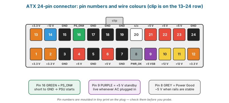
These colours and voltages are defined by the ATX specification and are consistent across standard ATX PSUs:
| Wire colour | Signal | Voltage | Tolerance |
|---|---|---|---|
| Yellow | +12 V | 12 V | ±5% (11.40–12.60 V) |
| Red | +5 V | 5 V | ±5% (4.75–5.25 V) |
| Orange | +3.3 V | 3.3 V | ±5% (3.14–3.47 V) |
| Blue | −12 V | −12 V | ±10% |
| Purple | +5 VSB (standby) | 5 V, present whenever AC is connected | ±5% |
| Green | PS_ON# | Pull to ground to switch the PSU on | — |
| Grey | PWR_OK (Power Good) | Goes to ~5 V when outputs are stable | — |
| Black | Ground | 0 V | — |
24-pin connector key pins: pin 16 = PS_ON# (green), pin 8 = PWR_OK (grey), pin 9 = +5 VSB (purple). (Some older or non-standard units differ; always check the label.)
The paper-clip (jumper) test
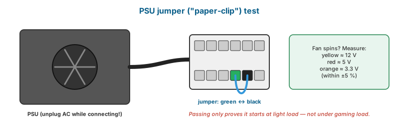
To check whether a PSU switches on without a motherboard: unplug AC, connect PS_ON# (green) to any ground (black) with an insulated jumper, connect a load if the PSU requires one (some PSUs will not start without load — a SATA HDD or a case fan will do), plug in AC and switch on. The fan should spin. Measure each rail with the multimeter.
Limitation: The paper-clip test shows the PSU turns on and gives correct voltages at light load. A PSU can pass this and still fail under load (voltage sag, shut-down while gaming). For load faults, use a PSU tester with load, swap with a known-good PSU, or monitor rails under a stress test.
Assembly procedure
Plugging the 8-pin PCIe (graphics) cable into the 8-pin EPS (CPU) socket. They look alike but are wired differently — check the label on the cable.
- Prepare the case: install motherboard standoffs only at positions matching the board’s mounting holes. A stray standoff touching the back of the board can short it.
- Install the CPU on the motherboard outside the case: align the triangle/pin-1 marker; for LGA sockets, lower the CPU vertically without sliding and close the load plate; for AM4 (pin-grid on the CPU) align and drop in with zero force.
- Install M.2 SSD(s) and RAM. Use the board manual’s recommended slots for two-stick dual-channel (commonly slots A2 and B2 — the second and fourth from the CPU).
- Apply thermal paste (a pea-sized dot in the centre is adequate for most CPUs) and mount the cooler; tighten in a cross pattern.
- Install the I/O shield (if not integrated), then the motherboard.
- Install the PSU, route cables: 24-pin ATX, 4+4 pin EPS CPU power (not the PCIe connector — they look similar but are keyed differently), SATA power.
- Connect front-panel headers (power switch, reset, HDD LED, power LED) per the manual’s diagram; front USB and audio.
- Install the GPU; connect its power.
- First boot: enter BIOS/UEFI setup, confirm CPU, RAM capacity and speed, storage detection, and temperatures. Enable XMP/EXPO for rated RAM speed if the customer wants it, and test stability.
BIOS/UEFI essentials
- Enter setup with Del or F2 on most boards (laptops: F2, F1, F10, Esc, or Enter then a menu key — varies by brand).
- Boot menu: commonly F12, F11, F8 or Esc.
- Key settings: boot order, Secure Boot, TPM (fTPM on AMD / PTT on Intel — required for Windows 11), SATA mode (AHCI vs RAID/Intel RST — affects whether the Windows installer sees the drive), XMP/EXPO, fan curves.
- Clearing CMOS (resets BIOS settings): use the board’s CLR_CMOS jumper/button, or remove the coin cell (CR2032) for a minute with AC disconnected.
Watch and read
- Watch: Complete PC build — YouTube search: how to build a PC step by step
- Watch: PSU jumper test — YouTube search: PSU paperclip test
- Read/use: TESDA Online Program (TOP) — Free self-paced online courses (about 40), including Computer Systems Servicing NC II and Start and Improve Your Business. No tuition.
- Read/use: Training Regulations: Computer Systems Servicing NC II (PDF) — The official standard: every competency, what the assessor checks, and the tool list. 280 nominal hours. Core: install and configure systems, set up networks, set up servers, maintain and repair.
- Read/use: Cisco Networking Academy (free courses) — Free self-paced Computer Hardware Basics (about 6 h), Operating Systems Basics and Networking Basics, each with a free digital badge.
Review questions
- Why might a new CPU fail to POST in a board that has the correct socket?
- Name the voltages and colours of the main ATX rails.
- What does a successful paper-clip test prove, and what does it not prove?
- Why must motherboard standoffs match the board’s mounting holes exactly?
Lab exercises
Lab 6.1 — Build. Assemble a complete PC from components, achieving POST and entering BIOS. Instructor checks cable routing and thermal paste application.
Lab 6.2 — PSU testing. Perform a jumper test on three PSUs and record all rail voltages. Identify any outside tolerance.