Laptop Motherboard Diagnosis
≈ 5 min read · Print / save as PDF
Power the board from the bench supply, read the current, then follow the power chain until you find the first missing voltage. That is where the fault is.
This chapter teaches the method for “no power”, “no charge”, and “power but no display” faults at board level. It requires: a bench power supply, multimeter, the board’s schematic and boardview, and a thermal camera if available.
Step 1 — Power on the bench supply
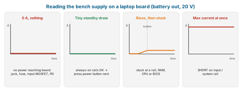
Connect the bench supply to the DC input (via the jack or a USB-C PD trigger/decoy board that requests 20 V), set to the adapter’s voltage (e.g. 19.5 V or 20 V), current limit about 3–5 A. Battery disconnected. Observe current:
| Current reading (no button press) | Likely meaning |
|---|---|
| 0 A | No power reaching the board: jack/port, input fuse, input MOSFETs, PD controller (USB-C), or charger IC not enabling the path |
| Small current, e.g. ~0.01–0.05 A (typical standby range) | Always-on rails probably present; press power button next |
| High current immediately, supply hits limit, voltage drops | Short on the input or system rail (B+/PPBUS), commonly a shorted input capacitor or MOSFET |
| Current rises on power button press, then stops at a fixed value | Board attempts power-up; stuck at a rail or waiting for RAM/CPU/BIOS |
| Current rises, falls, repeats (cycling) | Board starting and failing — protection triggered, BIOS problem, or RAM fault |
These ranges are typical observations, not specifications. Learn your own reference values by recording known-good boards.
Step 2 — Check for shorts (board unpowered)
Measure resistance and diode mode to ground on:
- Input rail (DCIN) and system rail (B+ / VSYS / PPBUS).
- Always-on rails (3VALW/5VALW or equivalent).
- Main rails: 3.3 V, 5 V, RAM, 1.8 V, 1.05 V.
- CPU core and GPU core rails (expect low but non-zero values; compare to known-good).
A rail reading near 0 Ω → locate the short using voltage injection (Chapter 3).
Step 3 — Follow the power sequence
With power applied, measure in sequence and stop at the first missing item:
- Input voltage after the fuse and input MOSFETs.
- System rail (B+).
- Always-on rails (powering EC and BIOS).
- EC alive? Check EC’s power pins and its crystal (32.768 kHz) if you have an oscilloscope. Check the power-button line (normally pulled high by a resistor, goes low when pressed).
- Press power: check sleep-state signals (e.g.
SLP_S5#,SLP_S4#,SLP_S3#) going high — these names are standard on Intel platforms; AMD uses equivalent signals. - Each regulator: input present? EN present? Output present? PG asserted?
- VCORE present after all others.
The first rail that is missing, with its regulator’s input and enable present, points at either a shorted output, a faulty regulator/controller, or a feedback fault. If the enable is missing, go back a step in the sequence.
Step 4 — Rails all good but no display
Possibilities: BIOS corruption, RAM fault (try known-good RAM or reflash/inspect soldered RAM area), CPU/GPU not initialising, missing reset or clock. Steps:
- Check that CPU core voltage appears and the board’s current draw reaches a normal “booting” level.
- Re-program the BIOS SPI chip with a clean image from the correct board (often recommended to dump the original first and preserve unique data such as serial numbers, MAC addresses and Windows licence keys stored in the BIOS region).
- Use a POST code card for laptops (some boards expose a debug port) where applicable.
Charging faults
| Symptom | Checks |
|---|---|
| Runs on adapter, won’t charge battery | Battery health; battery connector pins; charger IC settings; battery’s SMBus communication (SDA/SCL lines, diode-mode check); BIOS battery threshold settings |
| Runs on battery, not on adapter | Adapter; DC jack/USB-C port; input fuse; adapter-detection (ACOK/ACIN) signal; input MOSFETs |
| Charge LED blinks | Many brands use LED patterns as error codes (Dell, HP, Lenovo document these in their service manuals) |
Apple MacBook notes
- Intel MacBooks (2010s–2020): the always-on rail is PP3V42_G3H (3.42 V); the main system bus is PPBUS_G3H (typically around 12.3–12.6 V on these models; check the specific board). The SMC is Apple’s embedded controller. MagSafe/USB-C behaviour and fan behaviour are diagnostic clues.
- Apple-silicon MacBooks (M1 and later): the power architecture is different. Use the model’s board documentation. Firmware recovery for a Mac that will not boot is done with Apple Configurator on a second Mac (DFU “Revive” — reinstalls firmware without erasing data — or “Restore” — erases and reinstalls).
- macOS 26 (Tahoe) includes a Repair Assistant for Apple-silicon Macs, which completes post-repair calibration and pairing for certain genuine Apple parts — previously this required Apple’s own service software.
- Liquid damage is the most common cause of dead MacBooks. Corrosion near the SMC/EC area, backlight circuit, and the keyboard/trackpad connectors is common. See Chapter 16 for liquid-damage procedure.
GPU failures
Discrete GPU laptops with failing GPUs show artefacts, no display, or crashes under load. Diagnosis: test with the integrated GPU if the laptop allows switching (BIOS or MUX), check GPU core rail for shorts, check VRAM rail. Repair options: GPU replacement (BGA work), or for some boards, disabling the dGPU (if the design supports this). Be honest about warranty on reworked BGA.
Watch and read
- Watch: Laptop board no-power diagnosis — YouTube search: laptop motherboard no power diagnosis
- Watch: MacBook board repair walkthroughs — YouTube search: Paul Daniels MacBook logic board repair
- Read/use: Apple: Mac firmware revive and restore — Revive (keeps data) or restore (erases) an Apple-silicon or T2 Mac.
- Read/use: OpenBoardView — Free viewer for boardview files.
Review questions
- With no battery and the bench supply at 20 V, the board draws 0 A. List five likely failure points.
- Explain the sequence EN → output → PG in a regulator chain.
- Why should you dump the original BIOS before reprogramming?
- What is the always-on rail name on Intel MacBooks?
Lab exercises
Lab 11.1 — Power sequence mapping. On a working laptop board with a schematic, measure and record every rail and enable signal in sequence. This becomes your reference sheet.
Lab 11.2 — Fault injection. The instructor removes or shorts one component in the sequence (e.g. removes a regulator’s enable resistor). Students find the fault using the method above.
Lab 11.3 — BIOS programming. Dump, verify, and re-write an SPI BIOS chip with a programmer and clip on a scrap board.